


Energy Storage Systems Boost Electric Vehicles' Fast Charger Infrastructure


Electric vehicles (EVs) will gain more and more market share, eventually taking over internal combustion engine vehicles. Direct current (dc) fast charging stations will replace, or integrate, petrol stations. Renewable energies will be used to power them, such as solar and wind. People will desire to charge their EVs in less than 15 minutes and they won’t want to wait in a queue for a unique charging pile.
Considering multiple charging piles, the charging peak power that the grid will have to locally provide is more than 1 MW. The grid can collapse in many points, or huge investments are needed to improve the transmission lines and the central power plants needed to supply a much higher base load. This load, however, is impulsive and must be merged with the intermittent energy generated by renewable sources such as solar and wind.
Energy storage systems can solve this problem in a simple and elegant way. We use fluids like petrol or gasses to store energy and reuse it when needed (for example, when fueling a car). With the same principle, we can store electric energy in batteries using electrons and chemistry. This energy can be then utilized to boost an EV charge to keep the grid stable by shaving the peaks of power or to provide supply in case of blackout.
The mobility market is changing. Nearly 3 million EVs will be sold in the year 2020, on a total of more than 80 million vehicles. While this can look like a niche market, the forecasts are for a booming growth up to 10 million EVs sold in 2025 and more than 50 million in 2040, on a total of 100 million. This means, by the year 2040, 50% of sold vehicles will be fully electric. All these vehicles need to be charged slowly, overnight at home, with a simple wall-box or with a few kilowatt dc charger for houses with a solar generation system together with a storage battery, fast at the charging piles on the street, or superfast in future fuel stations.
Together with the rising EV market, we see that the renewable energy generation market—which has recently experienced booming years for solar photovoltaic (PV) systems—is still growing at a good rate, thanks to a price reduction of about 80% in the last 10 years and the push to decarbonize. Representing less than 5% of today’s global electricity generation, solar is expected to be more than one-third (33%) of the global electricity generation in 2050.
With a future made of intermittent loads, the EVs that need to be charged and intermittent energy sources—PV, as well as wind generation—present challenges such as how to combine these new players in the energy ecosystem, centered on the grid. Intermittent loads such as EVs will require extra dimensioning of the transmission lines to cover the higher power peak demands.
Solar production will change the way that central power plants operate to make sure the grid is not overcharged and that people will require easier access to electricity, and more and more self-usage of the electricity they produce at home will be with residential solar systems.
To make all entities work together smoothly and to benefit from the renewable sources and zero-emission EVs, energy storage systems must come into the game to make sure we can store and reuse the electrical energy that is generated when the demand is low (for example, solar energy generated at noon to be used in the evening) and to use the extra energy to balance the grid.
Energy storage systems (ESS) are the electrical equivalent of tanks for fuel or storage warehouses for coal. ESS can be used in multiple applications on both residential and industrial scale. In a residential application, it is simple to connect the PV inverter to the storage battery, to save and use the energy in the house or to charge the car overnight with the energy produced by the sun during the day. In an industrial- or utility-scale implementation, such as grid-connected services, ESS installations can be used for different purposes: from regulation of PV and wind sources to energy arbitrage, from backup support to black start (removing diesel generators), and, most importantly from a total cost point of view, investment deferral. In this last case, energy storage systems will be used to cover power peaks in the nodes of the grid, making sure the existing transmission lines don’t need expensive upgrades. Another relevant user case is the off-grid installation, where ESS enables microgrid or islands to be self-sufficient.
The ESS market, considering all its possible applications, will breach the 1000 GW power/2000 GWh capacity threshold before the year 2045, growing fast from today’s 10 GW power/20 GWh.
For this article, the focus will be on the ESS installations for the EV charg- ing infrastructure.
The ac charging infrastructure, both for private installations and for public ones, is simple but power limited. Level 1 ac chargers work at 120 V ac, delivering at maximum 2 kW; level 2 is capable of 240 V ac and 20 kW and the power conver- sion from ac to dc is, for both, demanded to the vehicle on-board charger. The ac wall box is rather a metering and protection device rather than a charger. The vehicle on-board charger, for cars, is always rated lower than 20 kW, for cost, size, and weight limitations.
On the other hand, dc charging enables the possibility to charge the EV at much higher power: level 3 chargers are rated up to 450 V dc and 150 kW, and the newest super chargers (equivalent to a level 4) can go beyond 350 kW and 800 V dc. The upper voltage limit is set to 1000 V dc for safety reasons when the output connector is plugged into the vehicle. While using a dc charger, the power conversion is made in the charging pile, and the dc power output directly con- nects the charging pile with the car’s battery. This removes the necessity of an on-board charger, with all benefits in reduced occupied space and less weight. Nevertheless, in this transition phase, when the EV charging infrastructure is still fragmented and different country to country, region to region, a small 11 kW on-board charger is mostly present in the electric cars, to give users the ability to still charge via an ac outlet if needed.
Increasing the charging power requires an increased operating voltage to make sure the current is kept within reasonable limits for the cable’s size and cost, and implies the necessity to properly design and dimension the microgrid or the subgrid where the charging stations are installed.
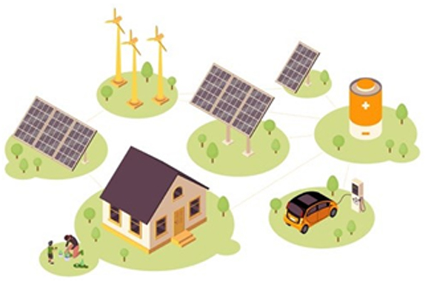
Let’s imagine a charging station of the future (in the year 2030), where the fuel consists of electrons and where the fuel is available from a pipe called transmission line, connected to the medium voltage (MV) grid via a transformer. Today the fuel is stored in big tanks underground and brought to the fuel station regularly by tank trucks. Having the new fuel—the electrons—always available from the grid seems an easy and issue-free solution, but we can see that this simple approach is not sustainable if we want to give drivers the possibility to charge their EVs in less than 15 minutes.
Our charging station has five dc charging piles capable of maximum 500 kW peak power output each. The worst case, for which the charging station must be dimensioned, is represented by five EVs charging fully depleted batteries at the same time. To simplify the calculation, we now consider zero losses in the power conversion stages and in the battery charging path. Later in the article, we will see how a proper design is influenced even by small power losses across the power chain.
Let’s consider five EVs, each one with a 75 kWh battery (the cars available in the market today, with a full electric powertrain, have batteries from 30 kWh to 120 kWh) that needs to be charged from 10% state of charge (SOC) to 80%:
5 × (70% × 75 kWh) = 5 × 52.5 kWh = 262.5 kWh
This means that an energy of 262.5 kWh must be transferred from the grid to the EVs in 15 minutes:
(262.5 kWh)/(0.25 h) = 1050 kW
Slightly more than 1 MW of power must be provided by the grid to the EVs, for 15 minutes. The charging process of lithium batteries will require a constant current, constant voltage charging profile, where the power required to charge up to 80% of the battery is bigger than the last 20%. In our example, we stop the charge at 80% assuming maximum power.
The grid or, better, the subgrid where the charging station is located, must sustain peaks greater than 1 MW intermittently. Very efficient and complex active power factor correction (PFC) stages must be implemented to make sure the grid is kept efficient, without affecting the frequency and without creating instability. This also means that very expensive transformers to link the low voltage charging station to the medium voltage grid must be installed, as well as making sure the transmission lines bringing the power from the power plant to the charging station are properly dimensioned to cope with the peak power required. In case the charging station is charging a mix of cars and trucks or buses, the required power is higher.
The simplest and most economical solution, instead of installing new transmission lines and big transformers, is to use the power locally generated by renewable sources, such as solar and wind. This enables users to have a direct link to the charging station with extra power and not rely only on the grid. Realistically, solar photovoltaic (PV) installations in the range of 100 kW to 500 kW can be done at the charging station or near the subgrid where the charging station is connected.
While the PV source can provide 500 kW, limiting the power requested from the grid down to 500 kW, the PV source is intermittent and not always present. This brings instability in the grid, as well as enabling the EV drivers to charge their cars at the fastest speed only when the sun is shining at its maximum. This is not what the users want, and this is not sustainable.
The missing piece of this power electronics puzzle is the ESS. Acting like the underground tank for the fuel in today’s stations, the ESS can be represented as a big battery capable of storing and delivering energy from the renewable sources to the grid or to the charging piles or back into the grid. The first key characteristic of the energy storage unit is being bidirectional and working on the low voltage side of the grid. The new installations will be targeting a dc bus voltage of 1500 V dc linking the renewable sources, the EV charging piles, and the ESS battery. A proper sizing of the ESS also has to be done to make sure the balance between peak power and energy capacity is optimal for the specific installation. This ratio strongly depends on the size of the local power generation, being through solar, wind, or other sources, the number of charging piles, other loads connected to the subgrid, and the efficiency of the power conversion systems.
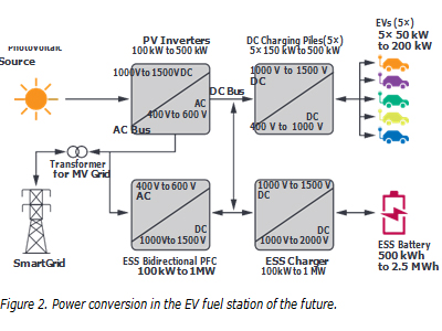
In this calculation, the energy storage system should have a capacity between 500 kWh to 2.5 MWh and a peak power capability up to 2 MW.
Having defined the critical components of the charging station—the sources, the loads, the energy buffer—an analysis must be done for the four power conversion systems that create the energy paths in the station.
The four power conversion systems are all sitting on the main dc bus, rated 1000 V dc to 1500 V dc. The higher the required power, the higher the dc bus voltage. 1500 V dc represents the industry standard today and for the next 20 years. While going at higher voltages is possible, this brings complications for the safety regulations, power components, and system designs, making it inefficient with the available technologies. That is not to say that in 10 years new technologies, such as power switches and protection systems, won’t make it possible to move to 2000 V dc or higher.
Considering the PV inverter, we see that it has a double function of a dc-to-dc converter—for the power path going from the PV panels to the dc bus—and the function of a dc-to-ac inverter—for the power path going from the PV panels to the ac bus and then into the grid. The dc-to-dc conversion stage is the most important here, since the ac-to-dc stage can also be integrated into the main bidirectional power factor correction (PFC) inverter going from the dc bus to the ac grid. Considering state-of-the-art power electronics designs, the highest efficiency is reached with converters designed around silicon carbide (SiC) power MOSFETs. The comparison with silicon insulated gate bipolar transistors (IGBTs) shows an efficiency increase in the range of 5% (maximum load) to 20% (partial load). In our example, with a PV inverter rated 500 kW, 5% better efficiency means 25 kW less losses or higher power output—the equivalent of five houses’ consumption or a big heat pump generating hot water or cooling the charging station building in the summer.
A very similar calculation can be made for both the dc charging piles and the ESS chargers. In both cases, two design approaches are possible: either big monolithic power converters rated more than 100 kW or many small converters rated 25 kW to 50 kW, used in parallel. Both solutions have benefits and draw- backs. Nowadays the multiple connections of small converters are leading the market because of lower costs due to economy scale and simplicity of design. Of course, a smart energy management system must be adopted.
Even for these dc-to-dc converters, moving from silicon IGBTs to SiC MOSFETs is bringing tremendous efficiency benefits, together with space and weight savings, at the cost of a slightly higher price—today 25% higher, expected to drop to 5% in the next five years. The efficiency gains alone can override this small price by saving (if we use the same 5% at maximum load):
(5% × 5 Charging Piles × 500 kW = 125 kW)
+ (5% × 1 MW = 50 kW) = 175 kW
Finally, in the PFC inverter, 5% of 1 MW is again 50 kW, bringing the total power savings, just because of higher efficiency of SiC vs. IGBT, to 250 kW. This is like having an additional charging pile or the possibility to better balance the energy consumption overtime vs. the actual demand of loads.
To achieve these results, as we said, SiC MOSFETs are needed, but they cannot solve the issues alone. The way the SiC MOSFETs are driven is key to reach the required switching frequency needed to have the best trade-off between system design costs (driven by the MOSFETs, the coils, and the inductors) and efficiency. The designers target the switching frequency in the range of 50 kHz to 250 kHz. The requirements for the gate drivers are becoming more challenging, mainly in terms of shorter propagation delays and improved short-circuit protection.
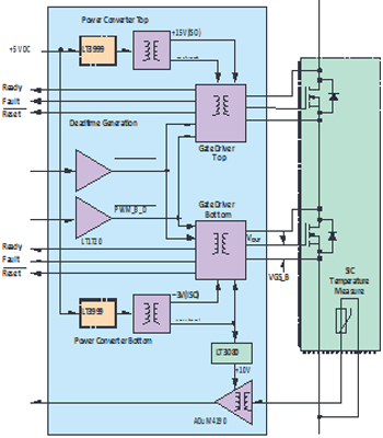
Analog Devices ADuM4136 is an isolated gate driver featuring the state of the art iCoupler® technology. This isolation technology enables a common-mode transient immunity (CMTI) of 150 kV/µs to drive the SiC MOSFETs in the hundreds of kHz switching frequency range. This, together with fast fault management like the desaturation protection, gives the designer the possibility to properly drive single or parallel SiC MOSFETs up to 1200 V.
The isolated gate driver must be powered, and in ADI Application Note AN-2016, we show how the combination of the ADuM4136 gate driver with the LT3999 push-pull controller represents a noise free, high efficiency building block to properly manage SiC MOSFETs. The LT3999 is used to control a bipolar isolated power supply for the ADuM4136. The ultralow EMI noise design of the LT3999 isolated power supply, together with the possibility to switch up to 1 MHz, enable a compact and cost-effective solution.
The total propagation delay, including the dead time plus the propagation delay, is 226 ns for the turn-on and 90 ns for the turn-off. The driver delay times are 66 ns for the turn-on and 68 ns for the turn-off, while the dead times are 160 ns for the turn-on and 22 ns for the turn-off.
The goal of having a very high power density in the power converters is achieved without compromising efficiency.
While power converters are fundamental for the power conversion paths, in energy storage systems, the key component to assure the best total ownership costs is represented by the battery managing/monitoring systems (BMS). In a price break analysis, we can see that for megawatt range energy storage systems, more than half of the cost is driven by the battery rack: about $200 per kWh today, expected to decrease down to $100 per kWh in 2025. Having a reliable and precise BMS solution enables the battery to extend its lifetime by 30%, resulting in a huge cost saving and simplified operability of the complete charging station. Less maintenance means longer working time and no issues for the users, thus increasing the safety level by reducing the connected risks of repairing.
To achieve these results, the energy management system that is controlling the energy flows around the charging station must have a very accurate understanding of the SOC and state of health (SOH) of the energy storage battery. Precise and reliable SOC and SOH calculations permit the battery lifetime to extend 10 years to 20 years in the best case, and in general a 30% lifetime improvement is achievable without increasing the electronic costs related to the BMS. This leads to a reduction of the operating and ownership costs of at least 30% given by the increased lifetime of the battery. This, together with higher accuracy in the SOC information, provides the ability to use all the energy stored in the batteries and to charge them in the best possible way, avoiding overcharging or overdischarging, conditions that can drain the battery out in a very short timeframe and create risky situations like short circuits and fires. For predictive maintenance, and to be sure the energy and power flows are properly managed, knowing the battery SOC and SOH means being able to predict and adjust the algorithms involved in the grid stabilization, in the EV charging process, and in the vehicle-to-grid (V2G) connection where the vehicles are also seen as storage units.
The solution for having accurate monitoring is to use a multicell—up to 18 cells—battery monitor IC with a total measurement error of less than 2.2 mV. All 18 cells can be measured in 290 µs, and lower data acquisition rates can be selected for high noise reduction. Multiple stack monitor devices can be connected in series, permitting simultaneous cell monitoring of long, high voltage battery strings. Each stack monitor has an isolated serial peripheral interface (isoSPI) for high speed, RF immune, long distance communications. Multiple devices are connected in a daisy chain with one host processor connection for all devices. This daisy chain can be operated bidirectionally, ensuring communication integrity, even in the event of a fault along the communication path. The IC can be powered directly from the battery stack or from an isolated supply. The IC includes passive balancing for each cell, with individual PWM duty cycle control for each cell. Other features include an on-board 5 V regulator, nine general- purpose I/O lines, and a sleep mode, where current consumption is reduced to 6 µA.
Due to the short- and long-term accuracy demands of the BMS application, the IC uses a buried-Zener conversion reference rather than a band gap reference. This provides a stable, low drift (20 ppm/√kh ), low temperature coefficient (3 ppm/°C), low hysteresis (20 ppm) primary voltage reference along with excellent long-term stability. The accuracy and stability are critical since they are the basis for all subsequent battery cell measurements and these errors have a cumulative impact on acquired-data credibility, algorithm consistency, and system performance.
Although a high accuracy reference is a necessary feature to ensure superior performance, that alone is not enough. The ac-to-dc converter architecture and its operation must meet specifications in an electrically noisy environment, which is the result of the pulse-width modulated (PWM) transients of the system’s high current/voltage inverter. Accurate assessment of the SOC and SOH of the batteries also requires correlated voltage, current, and temperature measurements.
To mitigate the system noise before it can affect the BMS performance, the stack monitor converter uses a sigma-delta topology, aided by six user electable filter options to address noisy environments. The sigma-delta approach reduces the effect of EMI and other transient noise, by its very nature of using many samples per conversion, with an averaging, filtering function.
In the ADI portfolio, the LTC681x and LTC680x families represent the state of the art for battery stack monitors. The 18-channel version is called LTC6813.
In summary, to address the challenges of the future dc fast charging infra- structure, the critical aspects will be in the power conversion systems and in the energy storage systems. Two examples have been proposed, the combination of the ADuM4136 isolated gate driver with the LT3999 power supply controller for the power conversion stages designed with SiC MOSFETs and the LTC6813 battery monitoring device for the energy storage batteries. Many more areas of focus are present in these systems, from the current metering to fault protection devices, from gas sensing to functional safety. They are all extremely important and bring huge benefits, and ADI is actively working in all these subsystems to make sure we can sense, measure, connect, interpret, secure, and power all the physical phenomena producing reliable and robust data—data that will be used by high end algorithms to make sure most energy is converted from renewable sources to the loads, in this case the electric vehicles.
About the Author
Stefano Gallinaro joined Analog Devices’ Renewable Energy Business Unit in 2016. He manages strategic marketing activities related to solar energy, electric vehicle charging, and energy storage, with a special focus on power conversion. Based in Munich, his business responsibilities span worldwide. Stefano studied electronics engineering at the Politecnico di Torino, Italy (BS) and began his career as an applications engineer at STMicroelectronics s.r.l.—Dora S.p.A., in Aosta, Italy. Before joining ADI, Stefano also worked as a product marketing manager at Vincotech GmbH in Unterhaching, Germany.
|
|